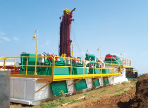
La máquina perforadora de túneles es una máquina importante en el proyecto de construcción de la ciudad, como el metro y la colocación de tuberías. Para llevar a cabo el corte y lubricar la broca de la máquina de túneles, los operadores deben agregar gran cantidad de agua o fluidos de perforación en el pozo de perforación. Para ahorrar costos, los operadores también tienen que pensar en reutilizar los fluidos de perforación.
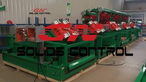
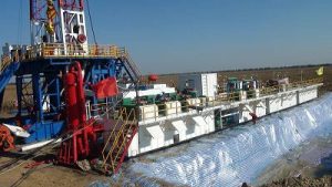
El equipo de reciclaje de lodo se utiliza principalmente para reciclar los fluidos de perforación y eliminar los recortes. El agitador de lutita, la lijadora y la lijadora podrían separar respectivamente los sólidos gruesos, la arena y el limo. Para sólidos finos, se necesitaría la centrífuga decantadora.
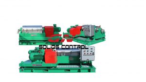
Después de varios tiempos de reciclaje, la gravedad específica de los fluidos de perforación sería cada vez mayor debido a la acumulación de sólidos ultrafinos que ni siquiera se pueden eliminar utilizando solo la unidad de centrifugado. Los operadores deben agregar químicos a los fluidos de perforación y luego realizar el proceso de deshidratación.
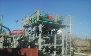
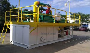
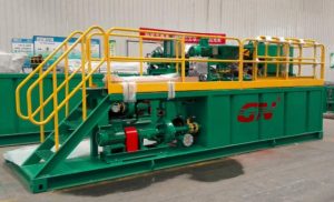
El paquete de centrifugado de deshidratación incluye 2 partes: sistema de dosificación de productos químicos y unidad de centrífuga decantadora de tazón grande. Las unidades listas para su envío a Singapur están diseñadas en contenedores con la centrífuga y la unidad de dosificación se colocan en el contenedor de 20 alimentos para facilitar el transporte y la seguridad en el lugar de trabajo.
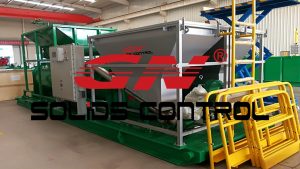
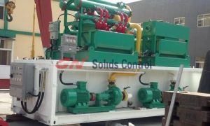
El sistema de dosificación de GN consiste en tolva de alimentación de polvo, tornillo de transferencia de polvo, tanque de mezcla y bomba de descarga. El tornillo es PLC para una medición precisa del polvo. El tanque de mezcla se divide en 3 departamentos para mezclar, curar y almacenar el polvo de floculación. El procedimiento de mezcla también es PLC para conveniencia automática. Antes de que los fluidos de perforación se introduzcan en la centrífuga decantadora, el agente de floculación se mezcla primero con los fluidos para recolectar los sólidos ultrafinos. Así, la centrífuga decantadora eliminaría el flóculo de los fluidos de perforación.
La eliminación de los sólidos ultrafinos de los fluidos de perforación reduce en gran medida el consumo de agua y aumenta la eficiencia de la perforación. El paquete de centrifugadora de deshidratación también se puede utilizar en el proyecto de tratamiento de fangos de aceite para la recuperación de petróleo.