El control de sólidos de GN está obteniendo cada vez más negocios de la industria de protección ambiental además de la industria de perforación. La mejora continua hace que los productos de GN se puedan utilizar en otros proyectos sin perforar el reciclaje de lodo y la gestión de desechos. Esa es la razón por la que GN se mostrará en la exposición de IE China 2018 en Shanghái.
Este espectáculo es para la protección del medio ambiente, y GN tendrá un stand y mostrará el equipo de fabricación propia allí. Por favor, escriba la información a continuación y visite el stand de GN para obtener más información sobre el control de sólidos de GN.
Fecha: del 3 al 5 de mayo
Ubicación: Shanghái New International Expo Center
Stand GN: W2 566
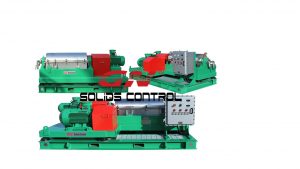
El equipo GN que se mostrará en la feria es una centrífuga decantadora y una bomba de vacío de lodo.
La centrífuga decantadora de dos fases de GN es un tipo de equipo utilizado para separar las partículas sólidas finas del líquido para limpiarlo. La centrífuga de decantación de GN se aplica para eliminar los recortes de perforación de los fluidos de perforación, para que los fluidos de perforación sean reutilizables. Debido al mismo principio de funcionamiento, la centrífuga decantadora puede utilizarse en proyectos de tratamiento de aguas residuales para separar los sólidos gruesos en las aguas residuales en las primeras etapas del sistema de tratamiento de aguas residuales. A veces, el agente de floculación se agregaría al agua residual para recoger los sólidos ultra finos, y luego se alimentaría a la centrífuga decantadora para su separación.
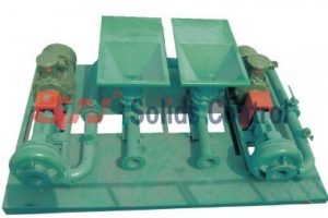
La bomba de vacío de GN se utiliza para una bomba completamente operada por aire que puede transferir alto contenido sólido y lodo de alta gravedad. En la protección del medio ambiente, la bomba se puede utilizar para transferir el lodo en el vertedero a la planta de tratamiento. Tiene una alta eficiencia para chupar desde 50 metros de distancia y descarga de 500 a 1000 metros. La bomba de vacío puede aspirar el lodo con un contenido de sólidos de hasta el 80 por ciento o con material seco completo como arena y tierra.