GN Solids Control – Limpiador de lodo

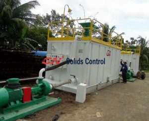
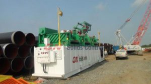
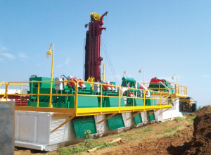
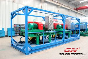
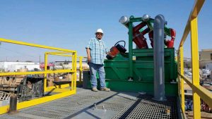
Los limpiadores de lodo forman parte de la tercera fase del sistema de control de sólidos. El limpiador de lodo se encuentra ubicado e instalado en la parte de arriba del tanque de lodo, seguido por los desarenadores. El limpiador de lodo esta compuesto mayormente por hidrociclones de 4 pulgadas, conjunto de colectores, manómetro y por un tragamonedas de arena. El limpiador de lodo manufacturado y diseñado por GN Solids Control incluye diferentes opciones ofrecidas a los clientes. Pueden ser fabricados sin el tragamonedas de arena, dependiendo de las necesidades del cliente.

El limpiador de lodo de 4 pulgadas es utilizado para remover sólidos entre 16 a 50 micrones. El cuerpo de los hidrociclones son los componentes principales de los limpiadores de lodo. La punta del cono se enrosca en la parte inferior del cuerpo de los hidrociclones. El orificio en la punta del cono es lo que determina el traspaso de fluido, siendo manipulada de acuerdo con las necesidades y finalidad del mezclado.

En un proceso de operación normal, el lodo es introducido tangencialmente por la parte interior de los hidrociclones a una alta velocidad ocasionando un efecto de torbellino dentro de los hidrociclones. Ese efecto de torbellino es lo que conduce la parte mas densa del lodo hacia las paredes del hidrociclón, mientras que las partículas más livianas se mueven hacia dentro del cono. Las partículas sólidas de tamaño grande son descargadas por la parte inferior del hidrociclón y pueden ser procesadas con mas profundidad para remover las partículas pequeñas y el liquido conservado. Mientras que la parte superior del hidrociclón descarga las partículas mas finas.

Los limpiadores de lodo pueden ser utilizados en diferentes tipos de aplicaciones como, por ejemplo: en perforaciones de petróleo que contienen lodo de perforación liviano, perforación de pozos de agua, perforadoras de túneles, etc.

GN Solids Control – Desgasificador de vacío

El punto de enfoque mas determinante de GN Solids Control se basa en la manufactura de equipos encargados de la separación de sólidos en la industria petrolera. Luego de mas de 10 años en la fiel búsqueda de desarrollo y mejoramiento de maquinarias a base de múltiple estudios e investigaciones, GN Solids Control logra ser determinante y liderar en la industria de separación de sólidos. GN Solids Control forma parte del “National High Tech company,” lo cual significa que beneficia a sus clientes, ya que en lugar de pagar el 25% de impuestos sobre la renta, solo tienen que pagar el 15% de impuestos sobre la renta. Esto es una gran ventaja para nuestros compradores al poder comprar a un costo económico productos de alta efectividad manufacturados por GN Solids Control.

El desgasificador de vacío es uno de los productos mas innovadores fabricados por GN Solids Control. Juega un papel importante restaurando las porciones de lodo, reduciendo el costo de perforación y estabilizando el rendimiento de viscosidad del lodo. El desgasificador de vacío y el resto de sus componentes están diseñados para actuar exclusivamente como liberadores de gases que se pudieran encontrar en la mezcla de lodo. La función del desgasificador de vacío permite continuar con la perforación aun cuando se esta trabajando bajo condiciones de alto peligro. Minimiza la posibilidad de alguna explosión causada por partículas de gas esparcidas por la mezcla de lodo. El desgasificador de vacío es un producto apto y eficaz para varios tipos de sistemas de purificación de lodo.

El desgasificador de vacío de GN Solids Control es monitoreado por un sensor que nivela, protege y controla la succión de fluidos. Este desgasificador de vacío también puede actuar como un gran mezclador del lodo de perforación, que a su vez ayuda y proporciona mas eficacia al tratamiento conducido al limpiador de lodo.

GN Solids Control – Centrífuga Decantadora

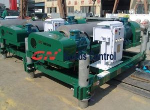
GN Solids Control se cataloga por su eficiencia y dedicación por revolucionar la industria petrolera con innovaciones de equipos y maquinarias. Se encuentra siempre evolucionando y avanzando de manos con la tecnología para no rezagarse. La Centrífuga decantadora es una de las maquinarias mas populares fabricadas y diseñadas por GN Solids Control. Cuenta con 5 modelos diferentes para suministrar variedad y opciones múltiples a nuestros clientes dependiendo de sus necesidades y requerimiento.
Esta la centrífuga decantadora de 220mm, es considerada una de las mas pequeñas de la industria. Mayormente utilizada para experimentos y pruebas, ya que aparte de que es económica, también beneficia a los clientes cuando sus espacios son limitados.
La centrifuga decantadora de 360mm, es una de las mas populares y vendidas por GN Solids Control. La centrífuga decantadora de este tamaño se caracteriza por ser utilizada en una gran variedad de tratamientos en la industria. Como, por ejemplo: tratamiento de aguas residuales, tratamiento de lodo y aceite, separación en la industria química, tratamiento de perforación de lodo, etc.
Luego se encuentra la centrífuga decantadora de 450mm, la cual tiene 3 opciones de tamaño en cuanto a la longitud del tazón. Esta la de 1105mm, la de 1540mm y la mas grande de 1890mm. Esta centrífuga decantadora es mayormente utilizada en tratamientos de perforación de lodo y es una opción económica también.
La centrífuga decantadora de 550mm, es utilizada en diferentes industrias. Tiene la capacidad adecuada para la mayoría de las plantas operacionales. Esto es debido a que cuenta con un tamaño mediano a diferencias de las demás modelos. Otra característica peculiar es que una de sus industrias de uso incluye, a la industria de separación alimentaria.
La ultima centrífuga decantadora fabricada por GN Solids Control es la de 760mm. Debido a su gran capacidad, esta centrífuga decantadora le permite al cliente trabajar con fluidos de mucho volumen tan solo utilizando una sola unidad. Es comúnmente utilizada en grandes proyectos como, separación de lodos de degrado, proyectos de túneles de perforación y limpieza de lodo, etc.
Todos los modelos fabricados y diseñados por GN Solids Control de centrífugas decantadoras, cuentan con muchas medidas de protección implementadas para darle larga vida y durabilidad a los equipos.

Own Brand, customized and international common shale shaker screen manufacturer

GN Solids Control is top 3 separation equipment manufacture certified by API in china since 2007. Our shale shaker screen. Over 10 years manufacturing experiences in shale shaker screen industry, now we not only produce for our own shale shaker, but also for international famous MI-SWACO shaker, Derrick shaker, Nov brandt etc. Furthermore, we also can manufacture according to customized requirement.

Our advantage for shale shaker screen:
1. Automatic Robot welding of the steel frame, which will reduce labor cost and the quality will be more stable and consistent.
2. High quality fiber glass, which will improve the screen quality and can bear high temperature to 140 c degree.
3. Four sides’ tension of mesh during heat press, which will minimize the gap between the top screen and support screen for long time use. Our competitors normally don’t use this kind of technology.
4. GN 3 layer wire mesh for API 60 and above, our competitors only can use 3 layer for API 120 and above, that is our strength.
5. GN high level wire mesh configuration is compliant to API RP 13C, which can be used for longer.
6. GN can produce not only for our own brand shale shaker, but also for many international famous brands, such as MI-SWACO, DERRICK, NOV BRANDT etc. Our shale shaker screen can be well compatible with those brands shale shaker.
7. Composite frame screen whose screen can be replaced, clean and reused, this will reduce cost, also increase its life. Besides increasing useable area 10% to 20%.
8. The composite frame is covered by plastic, it is easy to clean and can be stored for more than 5 years.
9. Flat and pyramid screens are available, this will give our customers more choice.

Shale shaker screen working mode:
Shale shaker screen is installed in the shale shaker; it can be used to filter drilling sludge and other industrial sludge. When sludge pass the screen, the particle smaller than the screen hole and fluid will cross over the screen and come into recycling, those particle bigger than the screen hole will be transported out. That is the working mode of shale shaker screen. Furthermore, customer can install two pieces of screens in one shale shaker, one screen is up and another is down, the up screen should be big mesh, and the down screen should be small mesh, but their gap shouldn’t be too big, such as up screen is 100 mesh, down screen is 80 mesh, this situation is ok, if up screen is 100 mesh, but down screen is 50 mesh, this will be wrong operation.

Now we have been exporting more than 70 countries, you can see our shale shaker screen everywhere. If you are interested in our screens, please don’t hesitate to contact us. We are available here to support you.

GN ‘s Third Party Equipment

The client has a preference for equipment from the suppliers specified by Section 7.1 and 7.2 of the Functional Design Specification.
GN is requested to source this equipment and these shall be priced separately. Should this not be possible, GN shall advise Company prior to award via the Exceptions Register and Company may elect to free issue these components.
GN may consider also quoting for alternative brands along with those requested. The following guidance is given:
• All alternative electrical products must be verified to have IECEx certification.
Pump Motors: Products must have IECEx certification. Contractor shall present a case to demonstrate suitability of the motors.
• Lights: Must be LED type, and of rugged construction suitable for oil rig environment.
• Sockets and Switches: Must be from a large supplier of well-known reputation for quality
• Butterfly Valves: Must include SS316 stem and disk. Only valves from a large supplier and of well-known reputation for quality will be considered.
• Pneumatically operated valves and controllers: Alternative brands will not be considered.
• Hammer Seal Unions: Must include the same thread and seal type as the Kemper product and components must be 100% interchangeable with the Kemper components. The client maintains an inventory of these components.
• Air Seal Unions: Must include a seal ring that is similarly 100% interchangeable with the Kemper seal ring. The client maintains an inventory of these components.
Pump Elements: Will only be considered if all components (for example the impeller and mechanical seal) are 100% interchangeable with NOV components.
Full product documentation must be provided for our review of any alternatives quoted. The performance characteristics of any alternatives must be similar to, or the same as the products specified. Section 11 of the Functional Design Specification can be used to reference the specified products performance characteristics.

GN Desander desilter pipe line group

mud cleaner is installed on the 2 # mud tank, 2 # mud tank is divided into four class. In four tank at the bottom of the separator is equipped with connecting highs of butterfly valve, butterfly valve with high when necessary in the open, connected to each other. Two SB8 x 6 sand pump tied for installation in 1 # mud tank end, respectively, in addition to the sand silt cleaner and cleaner provides the mud;1 # sand pump imports and 2 # mud tank 1 # tank is linked together, at work, extracting 2 # mud tank 1 # tank mud to desanding cleaner for solid-liquid separation, the overflow mouth ventilation with 2 # mud tank 2 # tank; The import of 2 # sand pump mud tank with 2 # 2 # tank is linked together, at work, extracting 2 # 2 # tank mud mud tank silt cleaner for solid-liquid separation, the overflow mouth bubbled into 2 # mud tank 3 # tank/submerged pump tank; In the submerged pump chamber equipped with submerged pump for centrifuge for pulp.

mud cleaner is installed on the 2 # mud tank, 2 # mud tank is divided into four class. In four tank at the bottom of the separator is equipped with connecting highs of butterfly valve, butterfly valve with high when necessary in the open, connected to each other. Two SB8 x 6 sand pump tied for installation in 1 # mud tank end, respectively, in addition to the sand silt cleaner and cleaner provides the mud;1 # sand pump imports and 2 # mud tank 1 # tank is linked together, at work, extracting 2 # mud tank 1 # tank mud to desanding cleaner for solid-liquid separation, the overflow mouth ventilation with 2 # mud tank 2 # tank; The import of 2 # sand pump mud tank with 2 # 2 # tank is linked together, at work, extracting 2 # 2 # tank mud mud tank silt cleaner for solid-liquid separation, the overflow mouth bubbled into 2 # mud tank 3 # tank/submerged pump tank; In the submerged pump chamber equipped with submerged pump for centrifuge for pulp.

Generally, between tank and tank high of butterfly valve is closed, the need to balance is open to open the mud.1, 2 # is sand pump can work independently, can also work at the same time; Through the open butterfly valve, can realize the sand pumping 1 # 2 # mud tank 1 # tank or 2 # tank mud; By the same token, the 2 # sand pumping 2 # mud tank 1 # tank or 2 # tank mud circulation.
In the import and export of every sand pump, equipped with butterfly valve and the soft connection, so that each of the sand pump repair or replacement.

mud pump suction pipe line.

Mud pump suction pipe respectively connected to 2 #, 3 #, 4 #, 5 #, 6 #, 7 #, 8 #, 9 #, 1 # tank;Between tank and tank with a scalable hammer type union is linked together, easy installation, reliable connection.As shown in figure 17 (mud pump suction slurry pipeline)

GN mud agitator

Drilling mud mixer is used in order to maintain uniformity of drilling fluid and solid particles suspension, and for continuous and reliable drilling mud of drilling fluid solid control system.
GN oil drilling fluid JBQ series mud agitator under 5.5 kW adopt cycloid reducer, JBQ series mud mixer is suitable for oil drilling fluid mixing, compact structure, cover an area of an area small;More than 7.5 kW drilling mud mixer adopts turbine worm reduction drive, has big transmission torque, smooth operation, reliable work, etc.Commonly used mixer model for JBQ5.5, JBQ7.5, JBQ11 and JBQ15.mud agitator shaft
JBQ mud agitator purposes and characteristics
JBQ series mud mixer adopts circular cylindrical worm reducer, shaft section for circular cylindrical worm, turbine tooth profile for round with turbine phase conjugate.So the concave and convex tooth and reliable performance, high efficiency, compact structure.
JBQ series mud mixer reducer combined with explosion-proof motor, easy maintenance, suitable for field use harsh operating conditions.
JBQ series slurry blender mixing intensity big, wide scope, and reduces the starting resistance.
Horizontal JBQ series mud agitator motor, installation, adjustment, easy to change.
Our company is specializing in the production of oil drilling fluid blender manufacturer, welcome customers to inquire.
Mud agitator installation and maintenance
1, the slurry blender when installation should be lifting mixer and placed in the position of the desire to install smoothly, adjust the coaxial degree < 0.39 mm will be 4 M16 hole only after welding on the tanks, fixed and tighten mounting bolts.
Rigid coupling must be equipped with 2, mud agitator trampoline and should be solid and reliable, otherwise it will cause a wave wheel shaft deflection, intensifying gear wear and tear.
3, mud agitator operation should be the same in the ring, cassettes, the high temperature anomalies.Otherwise should stop check, troubleshooting.
4, mud mixer reducer oil level height should be kept in the central visual oil window position, the work can often make up of lubricating oil.It is recommended to use 120 # industrial gear oil.When the site can not meet, also can use other size appropriate lubricating oil

GN vertical cutting dryer lubrication system maintenance

YLS machine is continuously lubrication system. With Timer, it can also used for intermittent lubrication. The lubrication viscosity between 30 ~250 cSt, new lubricating oil is required
Spit pressure can be max. 15kgf/cm². To protect the system peripheral, relief valve is equipped to keep the stability of lubrication system. When the oil level goes down the min, the lubrication system will give Alarm signal, or stop the dryer via external controller.
adding oil: Open the cover and add the clean lubricating oil, to 80% in oil level, then cover it. Only GN appointed lubricating oil or equivalent oil can be used
oil pipe connection: Take the casing pie cap and casing pipe out, put it on the oil pipe. Then, insert the oil pipe into the connection to avoid oil leakage.tumblr_m5a7omfwgO1qmyjkk
installation of power and alarm: Loose the screw and take out the cover of wire, there is pressure signal and level signal underside. There is a fixed head to fix the cable nearby. Rotate out the fixed head and get the cable through. Push it into wire cover and then fix the cable.
Connect the pressure signal and level signal. When the level close to Min. level, the level signal will give alarm; when the oil pressure reach to 2.1 kgf/cm², the pressure signal breakover.After finish the connection, cover the cable, fix the fixed head. If all the connection iscorrect, the lubrication system will work.
Note: the pressure switch and level switch is not ex-proof. Customer can do some actions to make it ex-proof.
pressure adjustment: Loose the screw of adjustment valve, (EX-works 15kgf/cm²), switch on the power. When the oil flow out 5~10s, then tighten the adjustment valve

Decanter centrifuge Installation and operation

GN solids control decanter centrifuge Installation
Centrifuge installation
1). Choose suitable lifting device and sling.
2). Cranes and slings can not bear excessive load, regular check shall be given to the slings so as to ascertain whether they are in good state.
3). The hall be checked before lifting to ensure that the strength of the sustained centers meet the requirement of hoisting.
4). Make sure the installation platform is firm enough to bear adequate weight.
5). Remove all the traportation protection device (bowl fixing belt, fasten belt and fixing bolts).
6). Connect inlet and outlet pipelines (use flexible joint for connecting point), overflow pipe, and solids discharge slot.
7). Connected with power supply (Switch controller between control panel and power supply is necessary to ensure safety of wiring).
Electrical installation
Warning:
A. Read carefully of centrifuge user manual and Control cabinet user manual before operating.
B. Strictly forbidden to open the control cabinet with power on. Only open the door after power cut off.
C. Any installation and inspection of electrics must be operated by professionals
The main motor, back motor and temp. sensors of VFD centrifuge has connected well to the aviation plug panel, users are supposed to connect cables with reference to VFD control cabinet user manual.
OperationGN decanter centrifuge
Preparation before operation
Ⅰ. Check below items to make sure all in good condition. Any abnormal conditions should be solved properly and in time.
1). Check and make sure all parts of the centrifuge assembled well.
2). Check and make sure the bowl fasten belts are removed.
3). Rotate the centrifuge bowl manually and check if there is any blocking or other abnormal condition.
4). Check and make sure the oil level of hydraulic coupler and gearbox is accordence with request.
5). Check and make sure the B-belt is suitably tensioned.
6). Check and make sure the belt covers and collection box top cover are closed well, bearing base, feeding pipe and control cabinet are screwed down well.
7). Check the 3-phase power supply is connected well.
8). Check the reset function of all switches, operating device, control bottom, and make sure they are flexible and in right position.
9). Check and make sure the control cabenit are mounted well.
10). When restart the centrifuge after long stop, measure motors with 500V megger insulation resistance, the centrifuge can be run only if the resistance ≥ 0.5 MΩ.
11). check and make sure the ground connection is reliable. Measure the grounding resistance if necessary.

Decanter centrifuge operation

Start the centrifuge temporarily to check the rotating direction. Change the phase conductors of the motor if the rotating direction is not correct.
1). Start and run centrifuge back motor in short time to observe whether the gearbox rotates in a correct direction, and make sure there is no adnormal condition occured.. Seen from the small end of the bowl, the gearbox shall rotate in counterclockwise.
2). Start and run centrifuge main motor to observe whether it’s pulley rotates in the correct direction, and make sure there is no adnormal condition occured. Seen from the small end of the bowl, the pulley shall rotate in counterclockwise.
3). Start in inching feed pump to observe whether it rotates in a correct direction. Observed from the end of the motor, the pump shaft shall rotate in clockwise.
Notice: ① Cut off the power immediately if the motor does not run after power to avoid it burn down
② When start the centrifuge, check whether the motor work continuously without abnormal noise. If the two motor could not work synchronously, operator should immediately shut
down the centrifuge for trouble shooting and then start the centrifuge again.
③ Motor is not allowed to start over five consecutively times in the cooling condition; When restart the motor after stop, it is not allowed to start over three consecutively times in the hot condition.
Ⅲ. No-load running
Start the centrifuge according to the operating steps, but do not start the feed pump to make it run without load. Check whether there is abnormal noise, vibration or heating. Make sure that the temperature rise of the bearing base is not over 35℃ after 2-hour running. If the condition permitted, measure the bowl speed and vibrating force of the bearing base and make sure that the bowl speed was not less than 97% of the rated figure and vibrating force was not over 7.1mm/s.
Ⅳ. Load running
Turn on centrifugal according to the operation steps, after it reaches the set speed, turn on the feed pump. Check and see if there is any abnormal situations e.g. abnormal vibration, noise, or heating, etc…
Choose the suitable pump feeding capacity according to the mud density & viscosity, and the performance requested to reach. DO NOT increase feed capacity sharply; it may cause block or the centrifuge and hold on the screw propeller badly.tumblr_m7aozdm0sr1qmyjkk